iPECS-MG Training – Station Feature
Power Point presentation for Station Feature of LG-Ericsson iPECS-MG. This is Part 3 from iPECS-MG Training Materials.
iPECS-MG Station Feature — Presentation Transcript
- Station Features Business Enabled Communications
- Contents • Introduction • Station Port & Station Number • DN Assignment • Call Coverage • Linked Pair / Group • Hot Desk • COS • Mobile Extension • Station VMIB Feature • VMIB Access • Call Recording • Phontage Backup/Delete • E-mail Notification • AME (Answering Machine Emulation)
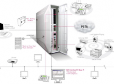
- Introduction Telephone Line (Physical Link) Telephone Line (Physical Link) Telephone (Physical Device) Telephone System Telephone Number (Logical Identifier or Link) Association between telephone and its number Normally, it’s one to one (1 : 1) Now, its one to N and N to one (1 : N, N : 1, N >= 1)
- Introduction A station (= terminal) can have multiple telephone numbers (DN: Directory Number). (1 : N = Terminal : Numbers) A number can be assigned to a single station or multiple stations. (1 : N = Number : Terminals) (Max. 10 Terminals) “Directory Number Assignment Example for two terminals” 1000 1001 2000 2000 2001 2005 Incoming Call : If there’s a call for DN ‘2000’, both stations will ring. Outgoing Call : User can choose one of the DN’s (‘1000’, ‘2000’ or ‘2001’) which is sent to the other station.
- Introduction Attributes for Station Port and for Station Number are separatedStation Port Attributes(Station Order 1~324)Station Number Attributes(Station Order 1~648)
- Station Port & Station Number Station Port Physical characteristics of the telephone can be defined. [Type] : DKT/SLT/LIP/SIP/DSS, [Attributes] : Headset, LCD Language, Flexible Buttons, … Max # of Station Ports : 120 (iPECS-MG 100), 324 (iPECS-MG 300) Stations can be ordered on a slot basis in PGM 103 – Station Logical Slot Assignment PGM 120 PGM 103 To configure port-related attributes (PGM120 ~ 126), use station number assigned to station terminal in PGM 103 (Default Number).
- Station Port & Station Number Station Number DN (Directory Number) : Telephone Number, Logical Number. Maximum # of digits : 8 Example) 100, 2000, 80000, 4504619, 70001000… Used in basic call-processing for station (making call & receiving call). Multiple numbers can be assigned to one physical port (Terminal). (N : 1) My-DN / Virtual DN / Prime-DN My-DN : Default Station Number (Station Order 1~324) It is automatically assigned when station slot is programmed in PGM 103. It can be also assigned to another station in the system (Linked Pair). Virtual DN : Additional Number assigned by system administrator This means extra DN that station owns. (Station Order 325~648) Prime-DN : Prime Number This number is displayed on LCD when station is in idle status. It has higher priority over other DN when station makes or answers a call.
- Station Port & Station Number Type of DN: SADN / MADN SADN : Single-Assign Directory Number SADN is allowed to be assigned to only one station. It can be used for intercom, command call, paging, multi-ring service and etc. MADN : Multi-Assign Directory Number MADN is allowed to be assigned to one or more stations (Max # 10). Relation Between Port & Number Relation Between Port and Number in iPECS-MG 100 (iPECS-MG 300) Port Index Station Number 1~ 120 (1 ~ 324) 1000 ~ 1119 (1000 ~ 1323) My-DN (PGM 103) 121 ~ 180 (325 ~ 648) 1120 ~ 1179 (1324 ~ 1647) Virtual DN (PGM 126, 130)
- Station Port & Station Number PGM 112 • • My-DN (Station Order 1~324) MG-300, Max Port : 324 • • Virtual DN (Station Order 325~648)
- DN Assignment Programmed on a Flex button. PGM 126 By default, My-DN is stored in each station’s flex button (BTN1) and it’s assigned as Prime Number Button. PGM 123 PGM 130 One MADN can be assigned to up to 10 stations. MADN can also be a Prime Number.
- Call Coverage via MADN MADN button on a station can be set only for incoming calls by disabling outgoing calls. If the MADN-type DN button has a delayed ring option, the button will operate as a call coverage button. PGM 130 Caller 1000 1001 2000 2000 Dials 2000 Station 1000 displays the number of 2000 on its LCD when idle. Station 1001 will ring for calls on 2000 immediately or with delay according to its ring option, but it cannot seize (or use) 2000 for making calls.
- Linked Pair / Group via MADN If a DN is assigned to various stations simultaneously and the DN is the Prime-DN of all of stations, they act like the same station. PGM 130 1000 1001 2000 2000 2000 2000 DN2000 using IN USE AT LINK STA 2000 ‘2000’ is displayed on the LCD of both stations since it’s their Prime-DN. If one is using DN2000, then the others cannot use DN2000. “IN USE AT LINK STA 2000” will be displayed on the others LCD.
- Hot Desk via SADN Assign Dummy Station – PGM 121-8 Dummy Terminal (ON) Assign Hot Desk Agent Number (PGM130) – Select (or Load) one DN in Virtual DN range (refer to Station Port) – Set DN type to SADN-HOTDESK * My-DN cannot be assigned as SADN- HOTDESK. Check Hot Desk Feature Code in Feature Numbering Plan – PGM 113-47 Hot desk Login/Logout To login through an inactive Hot Desk; 1) Lift the handset or press the [speaker] button, 2) Dial {HOT DESK Feature Code}, 3) Dial the user’s station number and password 4) Dial ‘*’ or press [SAVE] button. Then agent is logged in. To logout through the active Hot Desk; 1) Dial {HOT DESK Feature Code}. 2) Dial the call forward destination for Agent calls (Dial ‘#’ for not assigning the call forward) 3) Press [SAVE] button.
- Hot Desk via SADN PSTN During login Login Hot Desk Agent 1400 (DN Type : SADN HOTDESK) Login Dummy Terminal(1001) Hot Desk Agent 1401 Login (DN Type : SADN HOTDESK) During logoff Personal mail-box Hot Desk Agent 1402 Mobile Phone (DN Type : SADN HOTDESK)
- COS (Class of Service) via DN Class of Service : Dialing Restriction (16 classes) Dialing privileges can be assigned for each DN and CO line. 1) When an internal station dials out through a CO line. (Station to CO Case) 2) When an external caller tries to make another external call using DISA or DID. (CO to CO Case) COS Dialing Restriction 0 Intercom and Emergency number calls are allowed; incoming and transferred calls are allowed. 1 No restrictions are placed on dialing. 2 – 15 Assignments in each toll table are monitored for Allow and Deny numbers. (PGM 250) Toll Table Rule 1 – If a table has no entries, no restrictions PGM 250 are applied. Rule 2 – If there’s a match in deny table, allow table is searched again. If found, it is allowed. Otherwise, it is restricted. Example • Deny : 02 • Allow : 022500 Possible
- Mobile Extension on a DN basis Each DN can have 2 external numbers for its mobile extensions. [Service Mode and CLI] is for outgoing service while [CLI] is for incoming service Programming – Mobile Attributes (PGM236) : Mobile Flash Digit & Input Time – Mobile Extension Access (PGM132-F6) – Mobile Extension Number Access (PGM146) PGM 236 CO Grp Access Code + Dest. Num.
- Mobile Extension on a DN basis1) Incoming/Transferred calls routed to both desk phone and mobile phone simultaneously iPECS-MG ISDN DID Ringing 1000 Simultaneously Caller GSM Works in the office or out of office2) Outgoing calls can be placed using registered mobile phone iPECS-MG ISDN DID 1000 External User GSM Works in the office or out of office
- Station VMIB Feature on a DN basis Interaction with VMIB PGM 145 VMIB Feature Access Ability Recording Phontage Backup E-mail Notification
- VMIB Access on a DN basis – VMIB Access Feature Code (PGM 113-39) – not only for call forwarding to voice mailbox, but also for access to voice mailbox to retrieve (or manage) a message. Call Forwarding to Voice MailBox For Forward Destination PGM 143 Parameter to Voice Mailbox, this {VMIB Access Feature Code} can be used. Although some attribute require VMIB Access instead of {VMIB Access Feature Code}, for forwarding to Voice Mailbox, VMIB Access is just another expression of {VMIB Access Feature Code}. Voice Message Retrieval (ex) CCR Table (PGM260)) When Receiving Voice Message, Press [MSG/CALLBK] button or Dial {VMIB Access Feature Code} and Message prompt will be presented. For convenience, {VMIB Access Feature Code} can be assigned to Flexible Button. For password, enter station number + password + {#} sequentially.
- Call Recording on a DN basis – A Digital Phone User can record any active conversation including station call to the Station User’s Mailbox or to a Phontage Hard Disk drive or UCS Client. Two-Way Record To assign a flexible button as a {Two-Way Record} button. – Press [PGM] + {Flex} + {Two-Way Record Feature Code} + [SAVE] To activate Two-Way Record – While on an active Call, press {Two-Way Record} button. – When call recording begins, the station will receive a Call Recording confirmation tone. To stop Two-Way Record – Press {Two-Way Record} button again. Phone or UCS Client Station Number (If null, Recording Dest. is internal VMIB PGM 145 Auto Call Record If Auto-Record Service is enabled, Internal/External Call will be recorded without pressing {Two-Way Record} button. When a call is connected, both stations will receive a Call Recording Confirmation tone, and Conversation will start.
- Phontage Backup & Delete Phontage backup is available when messages are saved at VMIB boards. When ‘VM MSG Backup Phontage Number’ is assigned, the Phontage receives notification of voice mail for a registered Station. With Notification from VMIB (when new voice-message is arrived), the Voice Message count is incremented. Select Backup, the messages are downloaded to the Phontage PC’s hard drive ( Check VMIB & PC IP ) Phontage can delete voice mail on VMIB boards by selecting ‘Delete Msg’, according to its assigned authority.
- E-Mail Notification Voice messages can be notified by e-mail address associated with the Station as well as stored in VMIB. E-mail server address & Account Information must be defined. (refer to MS-Outlook e-mail account configuration) According to ‘Attach Message’ option, voice message can be attached to the e-mail as a .wav file. Even though the e-mail is deleted, the voice message in VMIB is not deleted. So it must be manually deleted from the VMIB as well.
- AME (Answering Machine Emulation) – When internal or external calls are forwarded to VMIB, the user can screen the call as if using a normal Answering Machine. LED Blinking Mode—When a call is forwarded to VMIB, the {AME} LED button will blink as notification; the user can hear saved voice conversations by pressing the {AME} button. Speaker Hearing Mode—When a call is forwarded to VMIB, the speaker automatically will be open to hear the calling party. The user can listen to the call, save it, or pick-up the call by pressing the {AME} button or {Mute} button. To assign a flexible button as a {AME} • How to make MUTE Button in a flexible button To assign LED Blinking or Speaker Hearing Mode. : PGM + Flex + 2(Fixed Key) + Select MUTE + SAVE – Press {AME] button, and Press 1 or 2 To Set Call-Forward to VMIB To answer a call in LED Blinking Mode. – When a call has been to forwarded to VMIB, {AME} Button will blink. – Press {AME} button to go to Speaker Hearing Mode. To answer a call in Speaker Hearing Mode. – Press {AME} button to communicate without saving conversation or Press [MUTE] button to communication while saving conversation.
- AME (Answering Machine Emulation) B. Speaker Hearing Mode A. LED Blinking Mode 1. Incoming call is diverted 2. [AME] button LED flashes 3. The call is heard to internal voice mail User presses [AME] button 4-1. If [MUTE] button is pressed, 4-2. If [AME] button is pressed, 4-3. If [MON] button is pressed, the call is connected the call is connected, but the telephone goes idle while recording is still in progress. recording is stopped. while recording is still in progress.
- Emergency Alert Emergency Alerting Service Any station user or Attendant can receive Emergency Call Altering in real time. [Emergency Alert] button is needed in flex button. Emergency Call information will be displayed on LCD (Emergency Code, Date/Time, Caller) Emergency Call History with [Emergency Alert] button. History can be check and deleted. System can store max 20 most recent Emergency Calls. Some internal user dial Emergency Code 1. All of [emergency Alert] Button will be flashed 2. Defined Alert Ring will be serve. Manager who a flexible button for [Emergency Alert] 1. Manager can check Emergency Call History with this button. 2. Emergency Code, Date/Time and Caller can be displayed 3. Manager can delete each history. – Emergency Alert Code – Feature Numbering Plan PGM113 – Emergency Alert Ring – Emergency Alert Ring Table PGM265 – Emergency Alert LED – LED Flashing Rate PGM234
LG-Ericsson: http://www.ericssonlg.com

Subscribe
0 Comments